Top 3 Essential Technologies for Ultra-mobile, Portable Embedded Systems
By: Chris A. Ciufo, Editor-in-Chief, EE Catalog
USB’s new universal Type-C connector, charging profiles, and super high speeds needing redrivers are among the change you’re carrying in your pocket.
Bigger screens, longer battery life, faster video gaming and dramatically better Cloud connectivity define the four legs of modern ultra-mobile embedded platforms like tablets, phones and other “smart, connected” devices. These must-have ultra-mobile features rely on three essential technologies:
- USB 3.1’s new universal “C” connector, that requires special crossbar and MUX ICs;
- Fast, intelligent charging over USB 2.0, 3.0, and 3.1;
- Gigahertz serial links that require redrivers for signal integrity.
These three essential technologies create challenges for designers. Tight, dense PCBs and high-speed serial links coupled with low output drive ICs mean signal integrity problems. USB charging profiles must take into account battery types, output current, and in the case of smartphones—how the manufacturer wants their battery topped up. Finally, USB’s “either side up” C connector is wonderfully convenient for consumers, but presents unique design requirements.
The Type-C connector is where our three trends come together. Let’s start there.
Lightning Strikes Twice?
Apple’s Lightning connector found on iPhone 5’s, 6’s and newer iPad’s is a marvel of analog and digital engineering. The 8-pin male connector is symmetric and can be inserted either way into its socket (up or down) while still maintaining backwards feature compatibility with Apple’s older 30-pin connector. Neat.
Because of USB’s ubiquity, the USB Interface Forum (USB-IF) is pulling a similar move with USB 3.1 and its new Type-C “All-in-One Connector.” At only 2.4 mm thick, it’s reversible at both ends while providing a multi-protocol 10 Gbps link and up to 100W for bi-directional device charging (Figures 1 and 2).
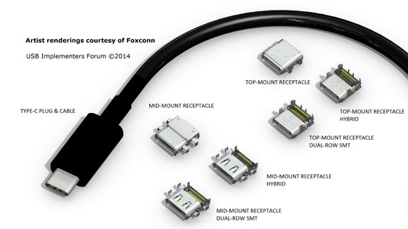
Figure 1: A detailed look at the Type-C cable end (male) and various receptacles. (Courtesy: Foxconn.)
 Figure 2: The 10 Gbps USB 3.1 Type-C cable is the same at both ends, and can be inserted up or down and send charging power in either direction. (Courtesy: Foxconn and USB-IF.)
The USB “C” Note
But unlike Apple’s Lightning connector, the Type-C isn’t just for USB. It accommodates myriad other end-cable types, speeds and protocols (Table 1). For example, HDMI and DisplayPort video can be transported across the Type-C cable at 5.4 Gbps, either natively or via a passive adapter cable plugged into the Type-C directly.
Other high-speed serial protocols are also possible with the Type-C connector (Figure 3). In short: “All-in-One” is an intentional design goal because designers envision the Type-C being used for laptop/tablet/smartphone docking stations connecting the ultra-mobile device to a breakout box containing legacy connections and peripherals for USB, HDMI, PCI Express, and so on.
 Table 1: Type-C USB 3.1 connector key characteristics.

Figure 3: Pictorial of the requirements for Type C: from 5 – 5.7 Gbps serial connections on DisplayPort or USB 3.0, to 100W charging of tomorrow’s high Watt-hour capacity mobile devices.
Yet the serial versatility of USB 3.1 and the asymmetric Type-C connector belies technical challenges. First, how does the system know what protocol is being sent on the wires? How can a system use the connector to transport USB 3.1, or PCI Express, or HDMI?
If the Type-C is our first essential technology, it’s only made possible with an underlying essential technology: the crossbar switch. A crossbar switch, under the control of the local CPU and USB 3.x host adapter, is used to send the appropriate signals over the Type-C. Figure 4 shows a computer or tablet docking station that supports seven comms channels: USB 3.x, four DisplayPort channels, USB 2.0, and low-speed UAR…all over Type-C.

Figure 4: Docking station example from a notebook, 2-in-1, or tablet. This configuration supports: USB 3.x, USB 2.0, four DisplayPort channels, and a low-speed UART. (Courtesy: Diodes Incorporated.)
Without a crossbar, the circuitry to support multiple serial interfaces on Type-C would be complicated because a number of discrete switches would be required. Diodes Incorporated, a supplier of high-speed interfaces and signal integrity products for USB, PCI Express, DisplayPort and others, has simplified the crossbar design with an off-the-shelf universal multi-protocol crossbar.
The PI3USB30532, listed as a Type-C USB3.0/DP1.2 3:2 differential crossbar switch on its datasheet, is actually protocol independent and can support USB 3.0, , 4 lanes of DisplayPort 1.2, and others. This is an ideal solution for a full-featured Type-C implementation. Also shown in Figure 4 is a nifty device that multiplexes the legacy USB signals D+/D- between their charging function and an alternate I/O channel—shown here for “lower speed” UART communications (lower than Gbps, that is). The Diodes' PI3DBS3224 is a 2:4 crossbar switch configured in this application as a 2:2 bi-directional crossbar switch capable of “low speed” operations at up to 1Gbps!
The clever use of crossbar and MUX/DeMUX single-chip ICs helps give the Type-C connector its “All-in-One” flexibility. Other devices supporting Type-C can be found at www.diodes.com/protocols/type-c/
Absolute Power
With European and other government mandates to reduce electronics waste, USB is designated the charging source and cable for myriad portable devices. USB 2.0/3.0 describes charging mechanisms in the Battery Charging BC1.2 specification, while USB 3.1 and the Type-C connector extends the USB-IF’s previous specification from about 2.0A (some manufacturers deviate) into the Power Delivery (PD) specification capable of 20V (100W). This 10x increase is more than ample to charge large portables with big batteries like laptops or test equipment.
In USB 2.0/3.0, charging power flows from Host to Device. In USB 3.1 using the Type-C connector and the new PD profiles, it’s no longer a given that charging current flows from the host port to a Standard Downsteam Port (SDP). In fact, power can flow in either direction—to/from Host or to/from Peripheral—depending upon the enumeration sequence. In some instances, your smartphone could charge your tablet, or vice versa. Other 3.1 changes: dynamic power delivery is possible so devices may use only the power they need; current can be ramped-up as needs evolve (such as application load or battery charging); and PD use cases and charging profiles now extend through USB 3.1 hub communications, too.
USB charging profiles, as defined by either the older BC1.2 or the PD specification, involves a choreographed dance on the D+/D- lines (for USB 2.0) plus CC1/CC2 (Configuration Channel) and VBUS on the Type-C connector’s signal lines. Based upon the enumeration challenge/response between the host and peripheral (or vice versa), the system knows how much current to deliver over the 5V VBUS line—from large batteries in 2-in-1’s to the small ones in wearables. This is accomplished using sensing, logic and charge circuits that must also coexist with regular USB communications plus any alternate channels (in USB 3.1). In summary: there’s a lot going on from cycle to cycle.
Figure 5 shows the charging circuit for a USB 2.0/USB 3.0 implementation. Note how it varies from Figure 4 by the omission of the CC1/CC2 signals found in USB 3.1. If USB charging is an essential ultra-mobile technology, then the underlying essential technology are smart USB chargers and control ICs. At the D+/D- and VBUS pins, smart IC’s such as the PI3USB9281C (device side) and the PI5USB2546A (host side) assure correct charging.
Both of these devices, though in small packages designed for use in ultra-mobile platforms like smartphones, support all USB charging profiles. They also support the proprietary profiles needed to charge the latest Apple and Samsung devices. In the USB 3.1 implementation shown back in Figure 4, the extra Type-C CC1/CC2 signal lines are monitored and controlled by logic control devices via the system’s

Figure 5: Standard charging via USB 2.0/USB 3.0 in a laptop powering an ultramobile device. Diodes Incorporated.PI5USB245x family is shown.
There are many nuances taken care of by these smart ICs in all USB charging scenarios, including: adjustable current limits, sleep-mode charging while the host or device are in standby, under-voltage lockout to prevent damage should insufficient charging voltage be available, keyboard/mouse wake-up, and proper implementation of the charging modes described in the USB-IF’s BC1.2 or PD specifications.
As an example, the PI3USB9281A, the IC used on the device side, can detect multiple types of chargers and profiles but supports both over-voltage/over-current protection while maintaining compliance to the USB 3.1 PD’s 20V voltage. It’s clear that it’s easier to use smart controller ICs than to roll your own logic.
Mind the Signal Gap
The third essential technology in ultra-mobile are the high-speed serial links we’ve been describing. But serial links won’t work all by themselves without the help of a redriver, our final underlying essential technology. That’s because at multi-gigabit speeds, transmission line effects become important and signals degrade, sometimes to the point of no longer meeting electrical specifications (Figure 6). Noise-induced jitter from clocks and other sources also wanders signals out of sync. In ultra-mobile devices with high-speed serial interfaces like USB 2.0, USB 3.0, USB 3.1, PCI Express 2.0/3.0, HDMI, and others like SATA or 10 Gigabit Ethernet, signal integrity (SI) is major design consideration. These GHz frequencies cause problems of cross-talk on adjacent traces, in buried PCB layers, or with non-back drilled PCB stubs.
 Figure 6: High-speed serial signals degrade due to all kinds of electrical and mechanical reasons. At GHz speeds, the source “eye” (left) is nearly closed at the receiving end. BER is so high that signals are out of spec. (Courtesy: Diodes Incorporated.)
As well, today’s smaller, die-shrunk processors, SoCs and intelligent peripherals found in space-constrained mobile devices have lower output drive voltage, so GHz signals can’t travel as far without degrading (due to lower swing ranges). So far, we’re describing a double-whammy: low drive coupled with (no pun) cross-talk and jitter.
It gets worse. The small or tiny motherboards and daughter cards found in ultra-mobile platforms present signal routing challenges. Savvy SI designers still have to route near “noisy” EMI sources such as RF circuits or antennas. As well, multiple circuit boards connected via flex circuits or internal cables force these weaker, cross-affected, and attenuated GHz serial signals to traverse multiple electrical boundary connections, each one causing reflections and causing further attenuation. Add one more insult in USB 3.1 implementations: the Type-C cable itself allows plug-on legacy adapters to older interfaces like DisplayPort, HDMI, and USB 3.0—adding yet another electrical boundary to further degrade signal integrity.
Re-Driver’s Seat
But there’s hope for all of these signal integrity challenges in ultra-mobile systems. Redrivers are small footprint active amplifiers that clean up and boost signals, recovering the margin and quality lost due to the SI challenges we’ve just described (Figure 7). Redrivers from signal integrity experts like Pericom are used in all kinds of portable devices—from smartphones to tablets— and they recover “generic” GHz signals.
More commonly, redrivers are designed to work with one or more protocols such as SATA, DisplayPort, HDMI or PCI Express. By tailoring the redrivers to the interface and protocol standard, intelligent features are enabled (such as bridging, switching, or packet routing), along with adaptive equalization or power management.
Diodes'PI3EQX862, for example, works with PCIe 3.0 and SATA 3.0 in the same system—perfect for portable SSDs like the kind used with 2:1 notebooks or built into tablet or smartphone cases for extra storage. Adjustable receiver equalization and input level signal detection/squelch assure maximum signal integrity.
 Figure 7: Long USB 3.0 traces on a dense ultra-mobility device PCB need redrivers to clean up signals and recover signal integrity problems. In portable platforms, external cables and flex circuits compound the SI problems. (Courtesy: Diodes Incorporated.).
And specifically in USB 3.0 systems such as shown in Figure 8, redrivers work internally and externally to assure strong SI. Designed for compliance with the USB 3.0 specification, Pericom states the company has “the only USB 3.0 redriver listed in the USB3.0 Integrators List”—providing confidence to designers that the devices not only work as advertised, but are all but essential in USB 3.0 designs. The a snapshot of how the redrivers work is shown in Table 2.

Figure 8: USB 3.0 redrivers used inside ultra-mobile devices…and outside. (Courtesy: Diodes Incorporated.)

Table 2: Some Features and Benefits of Diodes Incorporated. USB 3.0 ReDrivers.