The ReDriver ICs, also known as repeater IC, regenerate signals to boost the signal quality of high-speed interfaces. Faster signal frequencies leave designers with less signal margin with which to design reliable, high-performance systems. Using ReDrivers which have equalization, pre-emphasis, and other technologies that can adjust and correct for known channel losses at the transmitter and restore signal integrity at the receiver. This results in an eye pattern at the receiver with the margins required to deliver reliable communications with low bit error rates (BER).
ReDrivers (repeater ICs) are the key technology for addressing the rising design complexity that the higher data rates of today’s high-speed interconnects introduce across every industry and protocol.
To enable better signal integrity throughout the signal chain, Diodes Incorporated provides ReDrivers based on its industry-leading signal conditioning technology. ReDrivers offer better performance than protocol-based signal repeaters which act as an endpoint that must terminate and then retransmit the signal, thus introducing delay and added system cost. In addition, ReDrivers minimize jitter by conditioning and passing signals through the physical layer.
USB 3.2 with Power Delivery over USB Type-C (whitepaper)
Diodes Incorporated USB 3.0 ReDriver

Diodes ReDrivers address the five major issues negatively impacting the signal integrity of high-speed interfaces:
Signal Attenuation: High-speed signals, including differential signals, introduce noise and jitter that causes signal voltage swings to overshoot or undershoot the optimal eye opening. This results in a degraded signal during high-speed signal switching.
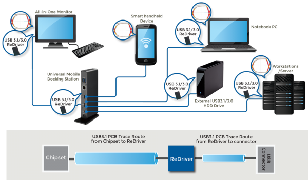
Signal Strength: Interfaces are increasingly being integrated into CPU chipsets. While providing excellent performance in the lab, many of these chipsets are often not strong enough to provide reasonable design margin to meet compliance specs when designed into real-world systems with multi-layer boards, long traces, and extended cable lengths.
Signal Distance: Layout constraints, controller-to-connector separation, multiple PCB layers, vias, daughterboard connectors, and extensive cable lengths all contribute to signal distance and greater signal degradation. For example, signal losses over FR4 PCB traces are typically 0.3dB per inch at 2.5 Gbps and 0.9 dB at 8 Gbps.
Noise: Both random and deterministic noise degrade signal integrity from a variety of sources, including crosstalk from other signals. Another common source of random jitter is a noisy clock source that does not have good isolation or has impedance mismatches.
Lack of end-to-end control: When an interface connects to an external subsystem or device, designers do have not control over the signal distance, board vias, connectors, and cables over which the signal must still pass to reach its destination. This can increase noise, jitter, attenuation, and insertion losses, and cause otherwise well-designed devices to fail to interface to equipment from other manufacturers.
The challenge for OEMs is that, as signal speeds increase, these factors become more pronounced, causing reliability, throughput, and quality to suffer. To help developers maintain signal integrity, Diodes offers unparalleled signal conditioning technology with a comprehensive portfolio of devices for PCI Express, USB, Thunderbolt, SAS/SATA, Bluetooth, Wi-Fi, HDMI, and other popular standards. Benefits include:
Superior Signal Quality: Diodes ReDrivers have the lowest jitter and attenuation for the highest performance in the industry. Comparative studies are available under NDA.
Lowest Crosstalk: By minimizing crosstalk, Diodes keeps channel-to-channel and part-to-part skew low.
Highly configurable: To provide developers greater flexibility, Diodes' ReDrivers can be configured on a per channel basis via an MCU over I2C rather than having to be pinstrapped or hardwired like other technologies.
Power Efficiency: These devices are architected for both low power operation and efficient power consumption. For example, Diodes' SAS/SATA redrivers consume less than 100 mW per channel and have the best power efficiency on the market.
Multi-port: Diodes' redrivers support a variety of multi-channels configurations, providing flexibility while enabling greater integration and cost savings.
Multi-protocol: Diodes' is the only manufacturer in the industry to offer a comprehensive portfolio of redrivers that work in both SATA and SAS environments.
Flexible packaging: Diodes' redrivers come in a variety of packaging options to meet the specific cost, performance, and power needs of your application. With devices on the order of 4 mm x 4 mm, these redrivers can be placed close the interface connector to minimize signal losses.
Improving signal integrity increases the overall signal margin of systems. OEMs can use this increased signal margin to:
Diodes' is the market leader in redriver technology across applications, including networking, embedded computing, and communications, among others. For example, in the server market, Diodes' was the first redriver manufacturer to achieve SATA3 compliance, and its technology has been adopted in more than 80% of server storage designs. Diodes' redrivers are also part of many controller vendor reference designs, including Intel.
As part of its commitment as the signal integrity leader, Diodes' offers unparalleled design support to its customers, including availability of evaluation boards, professional schematic and layout review, and system simulation to optimize the key opening using S-Parameter models, AMI-IBIS, or HSPICE.
High speed SAS 2.0, SATA 3.0, PCIe 2.0,PCIe 3.0, USB 3.0, DP 1.1 and DP 1.2
Yes, Pericom 3.0 ReDrivers PI3EQX8908A2, can be used in PCIe 1.0 and 2.0 modes.
Pericom PCIe 1.0 ReDriver™ does include a PCIe CLK buffer but neither the PCIe 2.0 nor 3.0 ReDriver includes a
PCIe CLK buffer.
Yes, Please contact your sales representative for simulation model and reference circuit. or contact Pericom Customer Support.
Our PCIe 3.0 ReDriver can perform output (ReDriver's TX) side 50-Ohm termination detect. The ReDriver's RX50 pin is asserted high once the device detects the 50-Ohm termination.
The PCIe ReDriver provides the signal output pin, "SIG", to indicate that signal is passing through the ReDriver.
Pericom PI3EQX7701 EQ can compensate 5 db and 11db loss (2.5 GHz or 5 Gb/s).
Please refer the AN233, page 5 and page 9.
No. USB 3.0 uses different connect pins from USB 2.0's. The USB 3.0 Standard-B receptacle interfaces are divided into two sets of interfaces: the USB 2.0 interface and the USB 3.0 SuperSpeed interface. The USB 2.0 interface is comprised of pins 1 to 4, and the USB 3.0 SuperSpeed interface is comprised of pins 5 to 9. The figure below shows the footprint of USB3.0 found in "Universal Serial Bus 3.0 Specification Version 1.0_Page 5-19_Figure5-8".
Not all obsolete parts will have a direct replacement. However, we recommended that you contact your regional sales office.
Yes, AN088 and AN233 are Application Notes for PCIe ReDrivers.
1Mohm pull down resistor on Pin 13 is needed on Dual Mode DP Source Device.
There are several types of jitter, but the main ones are: cycle-to-cycle jitter, period jitter, half period jitter, and peak-to-peak jitter. Jitter terminology can be found in AB36: Jitter Measurement Techniques at Application Brief No. 36 or Application Note No. 27.
Both I2C and GPIO controls are provided.
Emphasis control can improve USB3.0 ReDriver's output signal.
The integrated de-emphasis circuitry provides flexibility and improves the integrity of USB3.0 output signal after ReDriver.
The de-emphasis selection table below describes pin strapping options and associated de-emphasis operations. This table can be found in datasheet, page 3.
Emphasis control improves the PCIe ReDriver output signal.
EQ control can improve the USB3.0 ReDriver's input signal. The integrated equalization circuitry provides flexibility and improves the integrity of the USB3.0 input signal before the ReDriver. The Equalizer Selection table below describes pin strapping options and associated operations of the equalizer. This table can be found in PI3EQX7741AI datasheet, page 3.
Swing control can adjust the ReDriver IC output swing level.
Cycle-to-cycle jitter is the difference in the clock's period between two consecutive cycles and is expressed in units of + pico-seconds. This is because it can be either leading or lagging from the ideal output waveform.
A switch is a passive device with C-on and R-on that will attenuate the signal. A logic driver is an active device that will refresh an input signal at output by its active driving ability. Thus, compared to a logic driver, the maximum frequency of an application using a switch is limited by the trace length and the capacitive load. It is recommended to use a logic driver for applications with heavy capacitive load, long trace and high frequency.
The range of the impedance is from 75Ω to 105Ω.
All Pericom's products that are not lead-free are composed of 85% Sn and 15% Pb. For lead-free products, they are composed of 100% matte Sn. Lead-free products are marked and ordered with the letter "E" suffix at the end of the part number.
The minimum input swing level is shown in the specification "CML input Differential Input Peak-to-peak Voltage" and some ReDrivers can automatically select the input threshold voltage.
EQ control can improve the PCIe ReDriver input signal.
No, Pericom PCIe ReDriver will not block any PCIe signals. The ReDriver only enhances gains of the data voltage without changing the data. The host always sees the end-point directly. Pericom ReDriver is "100% transparent", which means the "host" and "end-point" do not detect the presence of the ReDriver.
FIT and MTBF data can be found at Pericom's Quality webpage.
Lead (Pb)-Free and Green information can be found on individual datasheets or Pb-Free & Green Page.